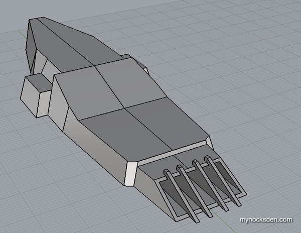
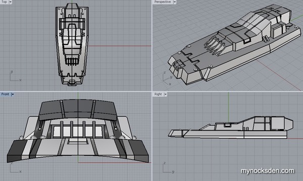
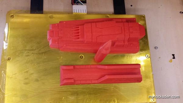
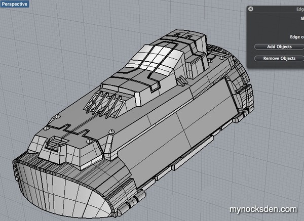
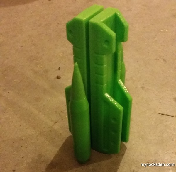
I began by modelling the flamethrower first. This is a pretty intricate piece, so I tackled the upper and lower assemblies separately, and then welded them together using boolean.
Half way through this piece, I had to wonder whether the concept artist who designed it looked to hair clippers for inspiration…
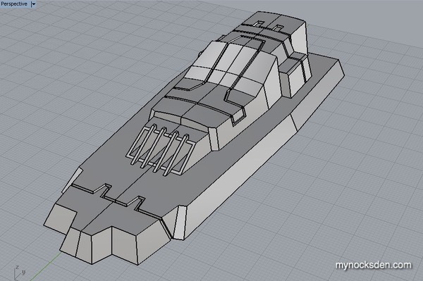
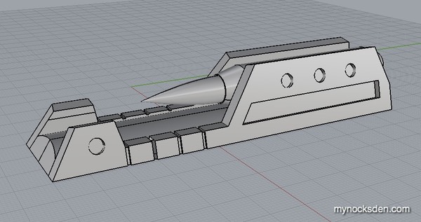
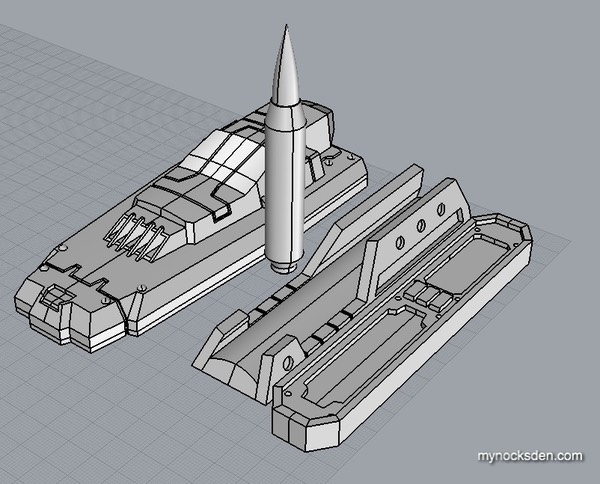
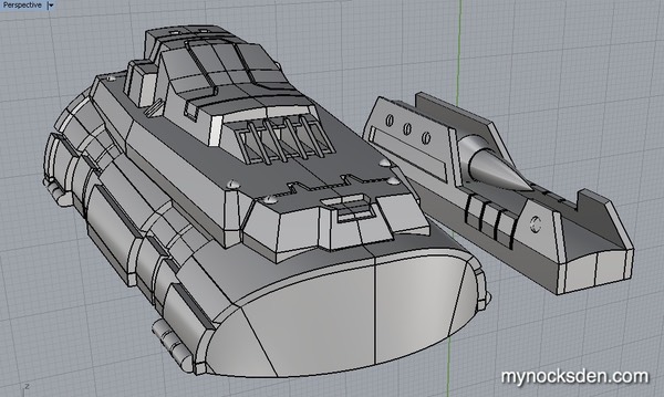
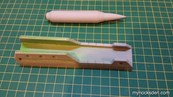
Next, I tackled the rocket launcher by modelling the main housing and the rocket as two separate pieces. I made the tolerances very tight so that the rocket could slide into the housing and be clipped in place by the two slanting side panels. (I got so carried away with it that I forgot to take progress screenshots).
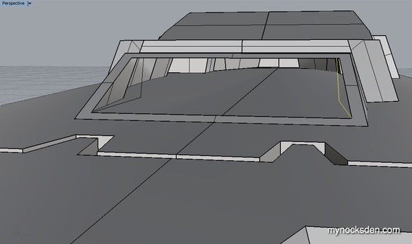
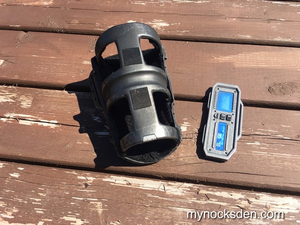
I did the elongated data readout screen last.
I then exported the rocket launcher and the flamethrower assemblies as one STL file and the readout screen as another, and printed them one after the other.
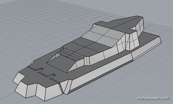
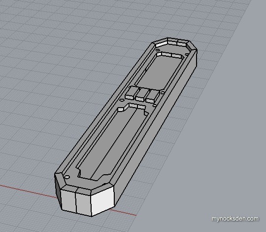
Right after I printed all this, however, I realized that it would be next to impossible to make the gauntlet base by hand without sacrificing detail. So, I set out to CAD model the rest of the gauntlet for 3D printing.
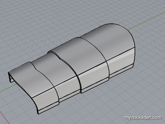
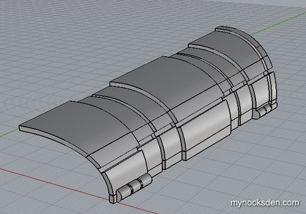
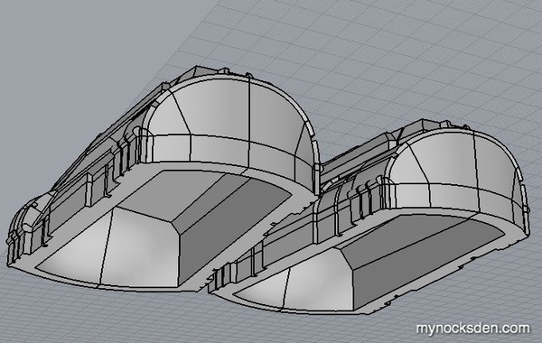
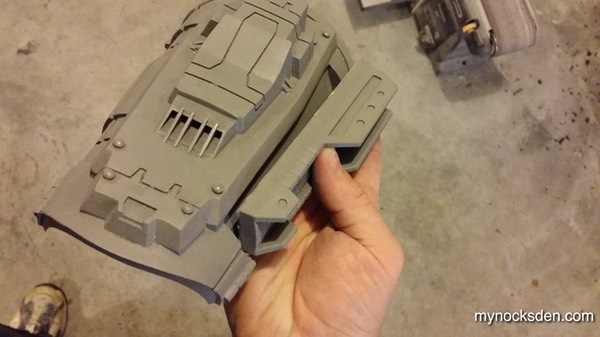
After many, many hours of work, the upper gauntlet was finished. The flat, recessed surface on the side (in next photo) is where the rocket launcher assembly (to be printed separately) would click in. This model would then be mirrored to make the gauntlet for the other arm.
Once the model was made 100% watertight, I printed the left gauntlet, rocket bracket, and rocket; it came out a perfect size for my wife, but a little too small for me. But, I figured tnat I could make it work. So, I went ahead and printed the other one.
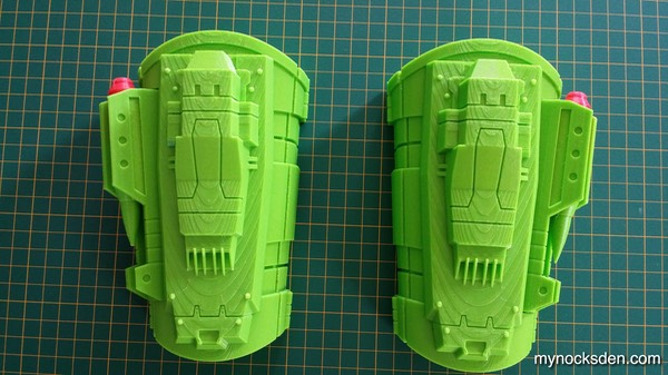
After a while though, it became pretty clear that the part would never actually fit me; I decided I should actually resize the gauntlets and printed the correct size. So, that’s what I did.
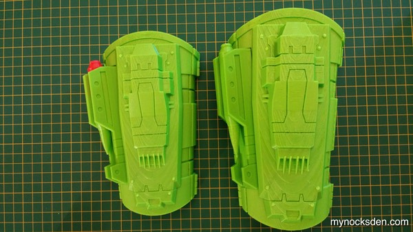
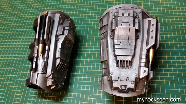
Here is a comparison shot showing the two sizes:
At this point the project was put on hold for a few months to focus on my Sith Acolyte build. Soon, however, the Shae Vizla itch returned, and I began to think about the vambraces again.
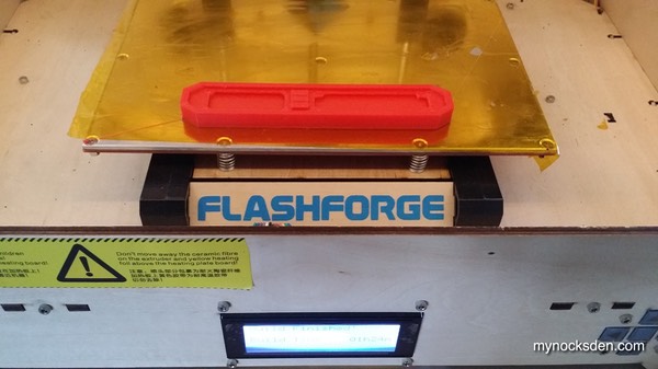
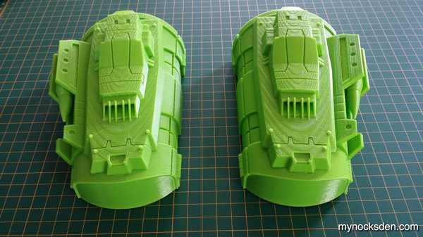
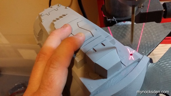
At around this time, I purchased my second 3D printer, the FlashForge Creator Pro, and started giving thought to reprinting the braces. The originals printed with a slight curl…
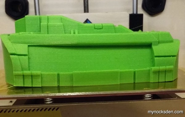
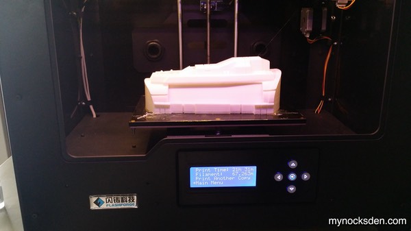
….so reprinting them with the new printer seemed like a good way to test out the new machine and hopefully get a better quality print. I tweaked the CAD models of the upper bracer to be hollow on the inside, like a tent, to eliminate the amount of plastic contacting the surface of the build plate and therefore reduce the possibility of curling.
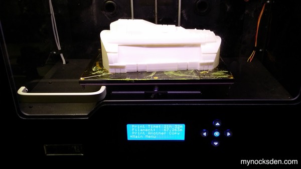
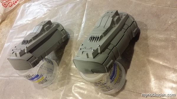
Approximately 43 hours later, I had my parts, which printed flawlessly!
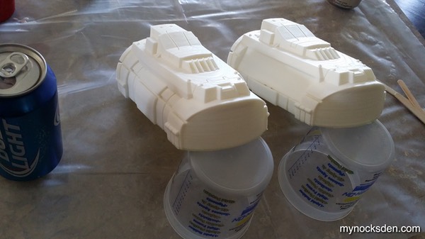
Normally, at this stage I begin to prep the 3D printed pieces for molding by using a combination of sanding, acetone vapour smoothing, and spot putty filling, however these pieces are so detailed, and have so many individual surfaces, that it would be next to impossible to turn them into proper masters for molding and casting using conventional means. So, I decided to spend a little extra money and time to transfer the shape to a softer medium, and do the prep-work on this.
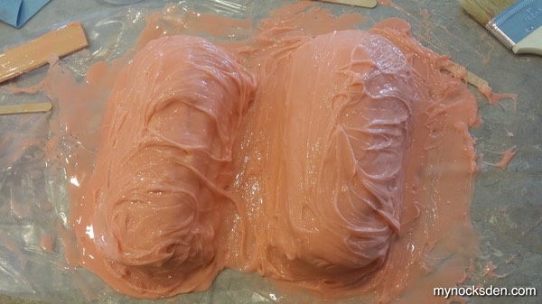
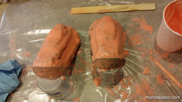
I prepped the prints for silicone molding by using SuperSeal followed by mold release to seal the surface (which, being untouched 3D printed ABS, is quite porous). I then elevated the nose of the models to allow silicone to run into the cavities between the flamethrower blades, whipped up some Rebound 25, and applied the first coat.
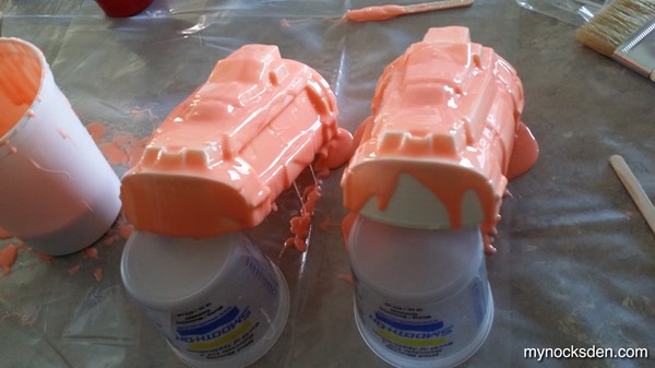
The next two layers were thickened with Thi-Vex, and allowed to cure overnight.
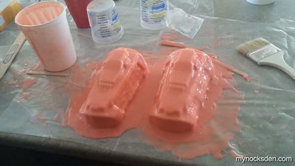
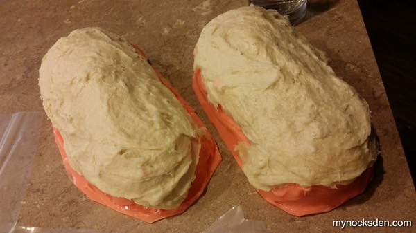
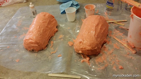
The following day after returning from work, I made a Plasti-Paste support shell, and put this in front of a heater to expedite curing.
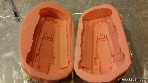
Demolding revealed a nice print coat, with only a minimum amount of bubbles in some of the deeper detail spots on the surface.
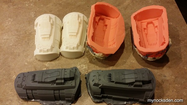
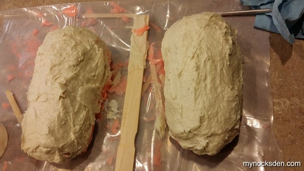
Next, I whipped up some 65D, coloured it with some So-Strong black pigment to give the castings a grey colour, and made a pull of each bracer. I made these very thick to allow lots of depth and strength for sanding, filling, etc.
Next came the tedious part that lasted about a week: each day I would sand a little, spot putty fill a little, prime, then sand and fill the imperfections some more, until the surface was as smooth and trouble-free as I could get it.
I had to sand off the 8 little rivet-like protrusions on each bracer to make it easier to work on the surrounding surface. Once the surface was clean and smooth, I used actual snapped off rivet heads to recreate this detailing.
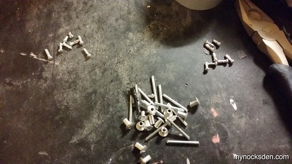
I carefully drilled 8 tiny holes into each model and inserted the rivet heads to recreate the original look.
After one of the most tedious periods in my entire time making props, the upper bracer masters were done, and ready for final molding. Using the exact same technique discussed above, I molded the two halves….
…and to my disappointment ended up with a print coat that was less than ideal. I noticed that the batch of Rebound 25 I’ve been using had started to become a lot more viscous over the past several months. Because of this, I ended up with very thick rubber mix, even without Thi-Vex thickener, which trapped some bubbles and messed up the print coat. It didn’t make the molds unusable by no means, but any castings obtained from the molds would have to be cleaned up mode than usual, which is always a pain. But, it is what it is… I may remould at some point in the future, but not right now.
Next, I tackled the missile and missile bracket. I acetone vapour-smoothed the parts...
...and used spot putty to fill in whatever areas didn’t smooth out well. After sanding and priming, I had the pieces ready for molding. (Initially I started out with two sets, but seeing as how the missiles and brackets are L-R identical, there was no point in molding both; only one set of molds would suffice).
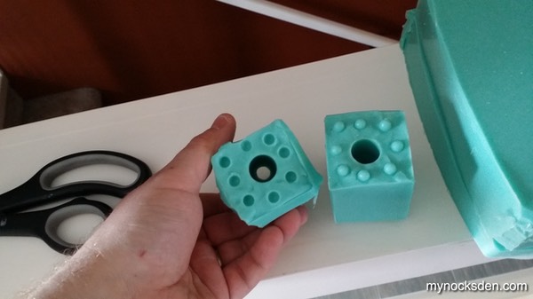
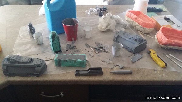
To mold the missile, I embedded half of it into plasticine, build a small box around it using scrap ABS pieces, and using the butt end of a pen made 8 indentations into the clay to act as registration keys. I sprayed the inside with mold release, and then poured in some Mold Star 15 silicone.
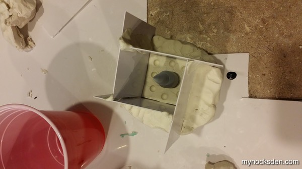
Once this cured, I removed the walls, flipped the silicone, peeled the plasticine off, added a long plasticine noodle to the butt end of the missile (to act as a pour hole opening),soaked every surface in mold release, and out of pure laziness of not wanting to build up the boundary box, dropped the whole thing into a red plastic cup, and poured in the silicone!
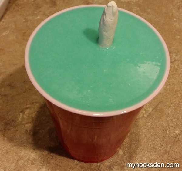
After this cured, I peeled off the plastic cup, cut off excess silicone with a utility knife, which revealed a nice, two part missile mold.
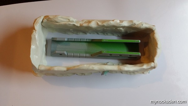
Next, I prepped the missile bracket for molding; since this piece has one dead side (with no detail on it), a simple pour mold is all that would be needed. So, I superglued the piece down to a piece of ABS sheeting, and built up boundary walls using plasticine.
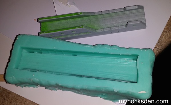
I sprayed the inside with mold release and poured in Mold Star 15. Four hours later, I had my mold.
Now that all the upper vambrace pieces were molded, it was time to cast! Using Smooth Cast 65 D as the medium and aluminum powder as the additive with a few drops of So-Strong black pigment for coloration I cold cast the upper bracer, missile, and the missile bracket.
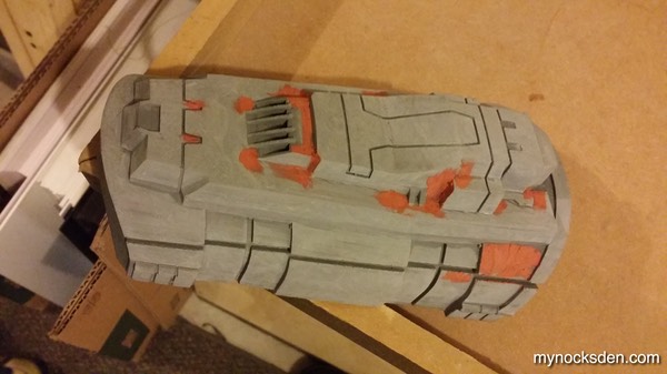
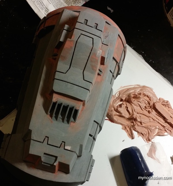
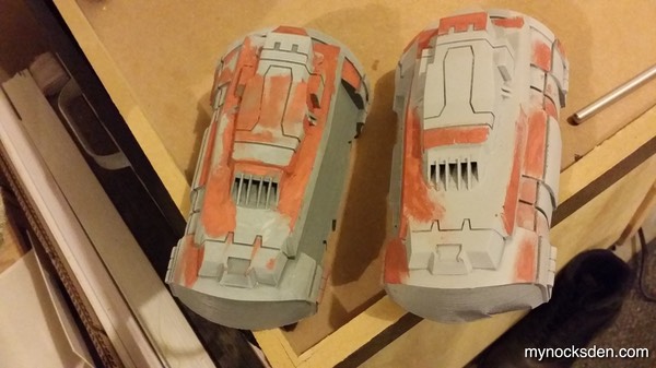
I then began trimming and sanding all the pieces…
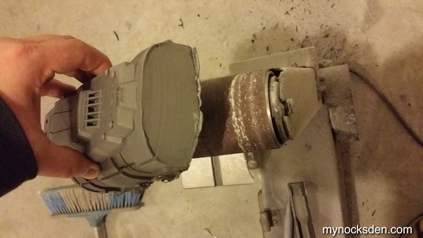
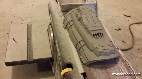
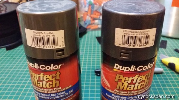
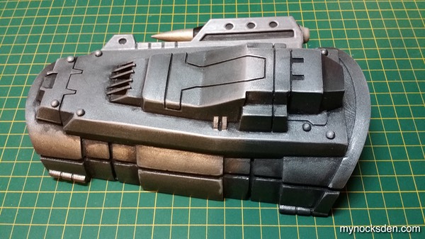
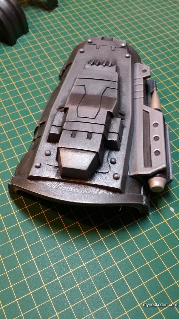
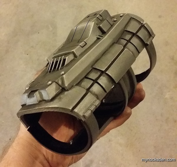
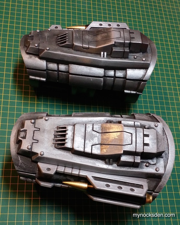
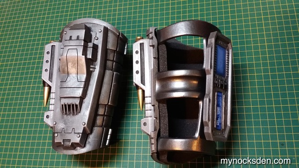
…and finally applying coats of Gray Metallic and Gunmetal Metallic Dupli-Color paints.
I then used steel wool and sandpaper to take some of the paint off along corners and edges, and used black acrylic, water based paint to paint the recessed areas and seams black. The missile was painted with Dupli-Color gold, and Krylon black. The missile bracket was then fitted and superglued into the upper bracer half, and reinforced from the other side with screws.
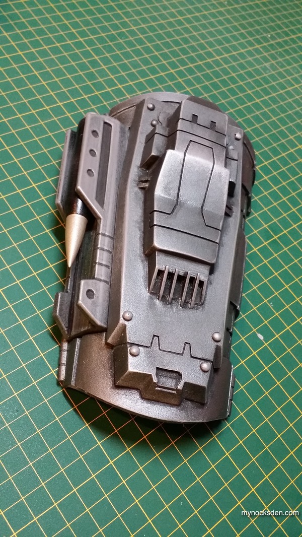
The missile was fit into the bracket, and secured in place with a screw from the bottom.
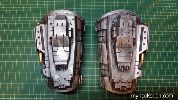
This completed the upper bracer assembly!
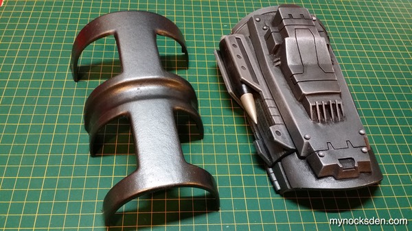
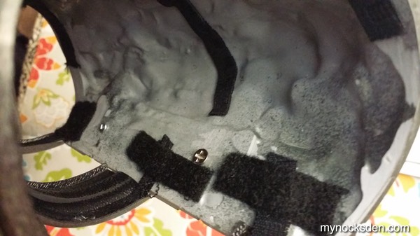
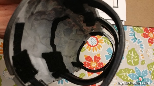
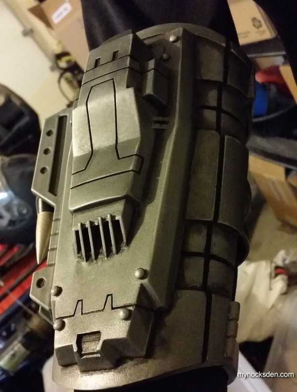
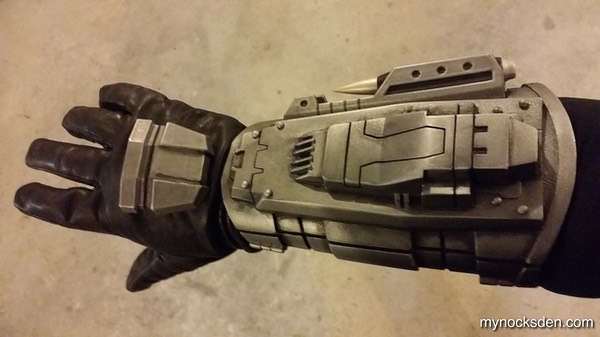
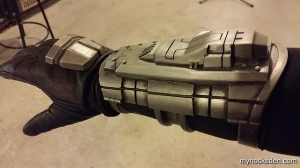
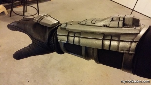
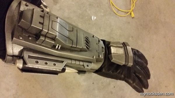
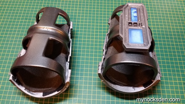
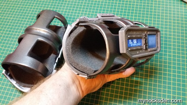
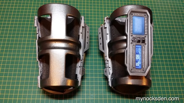
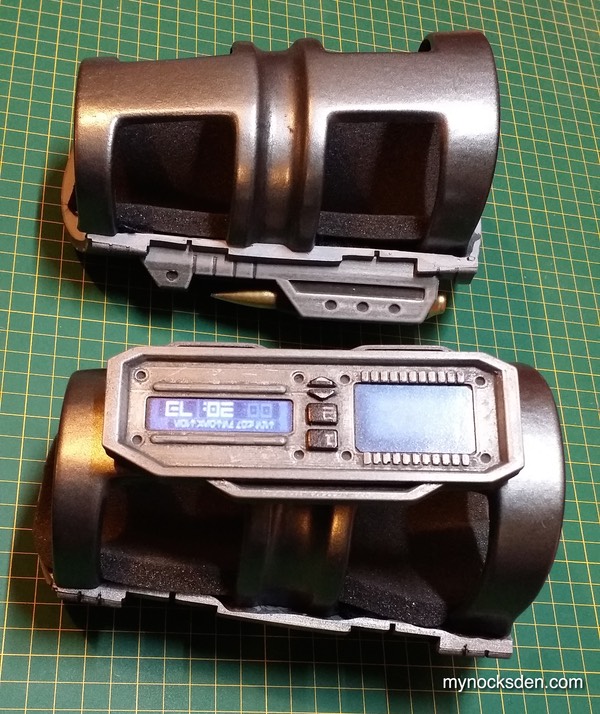
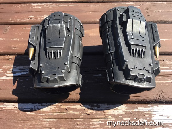
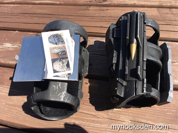
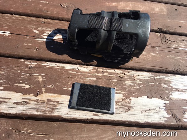
And here are some photos of the finished vambrace with the lower and upper halves combined. The two halves are attached with elastic straps, which are superglued in, and secured further with velcro strips, and padded using 1/2” open cell foam.
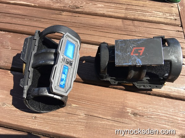
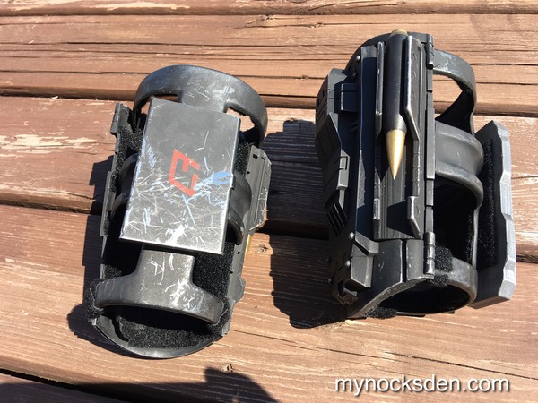
The left vambrace was made using the exact same process as the right described above, with the exception of a small datapad that is attached to the bottom half. For production notes on the bottom halve of the vambrace, click here.
And the “Mynock” Mandalorian armor colour variant:
All in all, this was by far the toughest and most time-consuming part of any build I have ever done. Here is a quick visual summary of the entire vambrace creation process and a legend that provides a reader’s digest version of the above process.
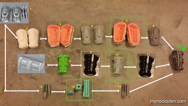
1) Vambraces are CAD modelled;
2) Uppers 3D printed;
3) Uppers molded to transfer the shape from ABS to a softer, more workable medium Smooth Cast 65D;
4) Uppers are cast in 65D, and are sanded, filled, and made into a final master;
5) Masters are molded again;
6) Uppers are cold cast in aluminum, trimmed, sanded, and painted;
7) Lower brace is CAD modelled;
8 ) Lower is 3D printed;
9) A HIPS sheet is vacuum formed directly over the 3D printed lower brace;
10) The HIPS shell is then filled with SC65D, which is then sanded and sharpened, to turn it into a buck for vacuum forming;
11) A final lower bracer is pulled using .06 black ABS sheet and trimmed;
12) Missile bracket and missile are 3D printed, smoothed, and turned into masters for molding;
13) Missile bracket and missile are molded;
14) Missile assembly cold cast in aluminum using SC65D;
15) Vambrace is painted and assembled using superglue, screws, elastic straps, and Velcro;
The steps that have a green box around them is the point at which successful replication of raw casts or pulls can begin for making multiple sets of items.
Thanks for looking!
* * * * * * *
Back to SWTOR Shae Vizla Bounty Hunter Gauntlet Assembly