
Tools for the Job
If you are interested in building your own EAS, here is the list of things you will need.
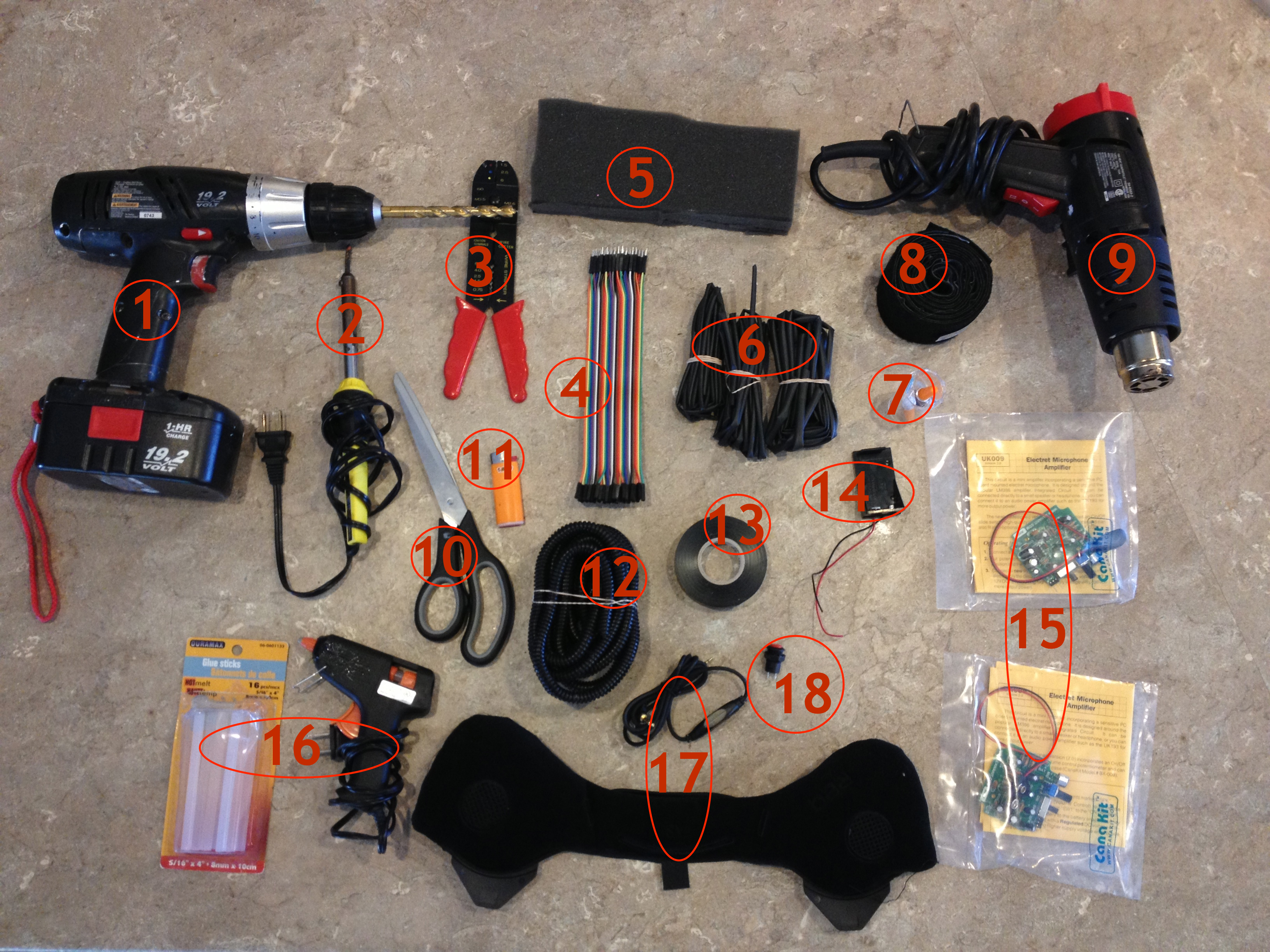
1. Drill with a 3/8 drill bit (3/8 is the exact diameter you will need to dril to fit the electret microphones through the helmet wall)
2. Soldering iron and solder
3. Wire crimp tool
4. Male - Female Dupont wire (I used 20mm length, though you can use 30mm as well; look on eBay - I bought hundreds for just a few bucks!)
5. 1" thick foam (or any other kind of semi-rigid padding material)
6. Heat shrink wire tubing (I used 3 different diameter types)
7. Superglue (save your money, and buy the dollar store kind!)
8. Industrial sticky velcro (hook and loop)
9. Heat gun
10. Scissors
11. Lighter
12. Loom (optional, but makes organizing wires easy)
13. Electrical tape
14. 9v battery holder (you can get 10 of these for $10 on eBay).
15. Electret microphone amps from Canakit.com
16. Glue gun and glue sticks (dollar store)
17. Ear pads with earphones in them (<-- google this phrase, and see your options). I used Burton Red Snowboard Helmet Audex Audio Earpads kit.
WARNING!
I am NOT an electronics expert, and in fact would classify my knowledge of electronics as less than amateur. The way I do things isn't "right" by any stretch of the imagination; therefore, what I am about to demonstrate only shows "how I DID IT", and not necessarily how YOU SHOULD do it. If you know a better or more correct technique for soldering / desoldering / connecting wires/crimping etc., by all means use that! If you don't, then doing what I did will at the very best give you the same results I got in doing this project.
18. Push on/ Push off (latching) switch (eBay)
* * * * * * *
Modifying the Speaker Setup
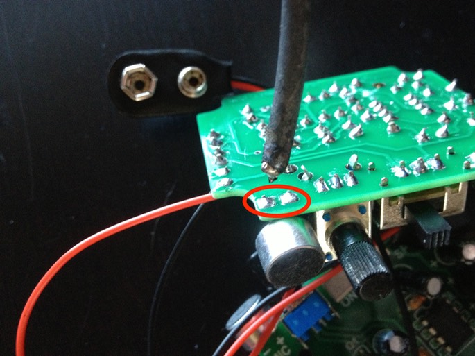
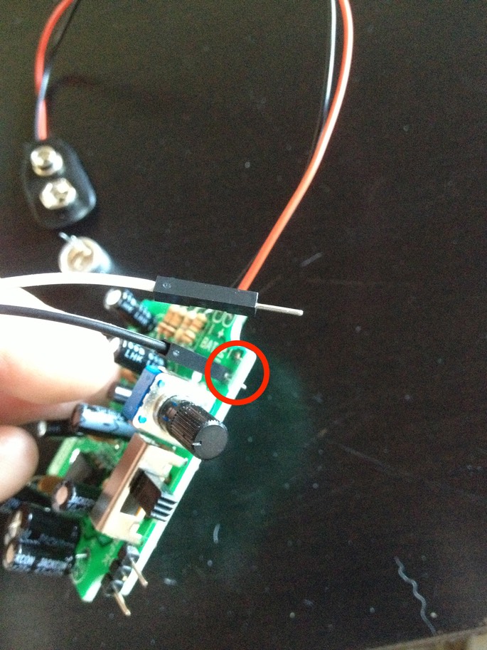
First thing I did is desolder the microphone that is hardwired onto the circuit board. Using a soldering iron, I applied heat to these two contact points until the solder melted, and pulled the microphone off the board. (You may need an extra pair of hands for this since heating the solder and pulling the microphone must pretty much be done at the same time. The mic should slide out smoothly; if it doesn't, the solder it still hard, and any wiggling or bending of the contacts will snap the microphone connectors.)
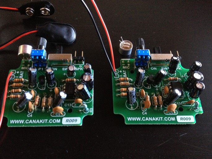
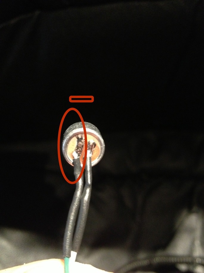
After the microphoned came off, it looked like this (on the right):
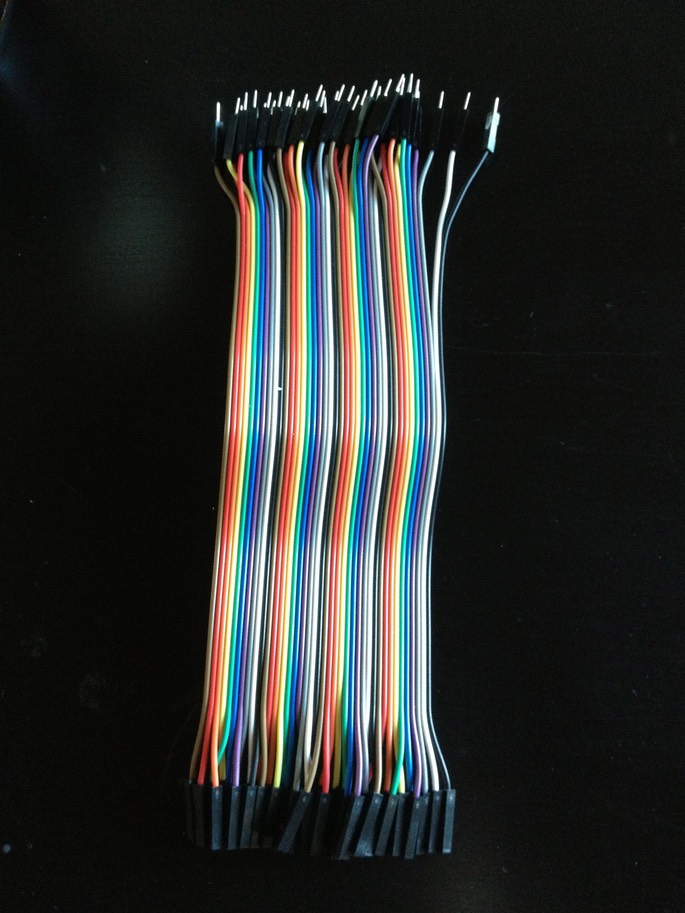
Next, I wanted to put the microphone on a wire, for which I used the 20mm m/f Dupont cables. These wires are dirt cheap, and are fantastic for making quick connections with the use of the male/female ends (especially handy when making connections to these AMP boards, as we shall see in a moment). In situations where you don't need the connectors, just cut them off, and use the cable as regular wire.
The ones in the photo came in a bundle of 40, which allows you to peel them off one by one, or in strands of 2, 3, 5 etc. For the next step, we will need to peel off a strand of two.
With the microphone removed, I heated up the now microphone-less solder joints as before, and at the same time inserted the male end of the Dupont cable into the hole about 3/4 of the way in.
You don't want to insert it all the way in, as you want to allow some room for the male pin to bend forward in order to decrease the vertical profile of the board, like this:
Next, I cut off the female ends of the cables I just attached, stripped the ends using the wire stripper tool, fit a little section of heat shrink tubing over each end, and soldered the ends to the appropriate microphone "leg" terminals. If you are not certain which is which, the negative is the one with a little tab that runs under the microphone housing.
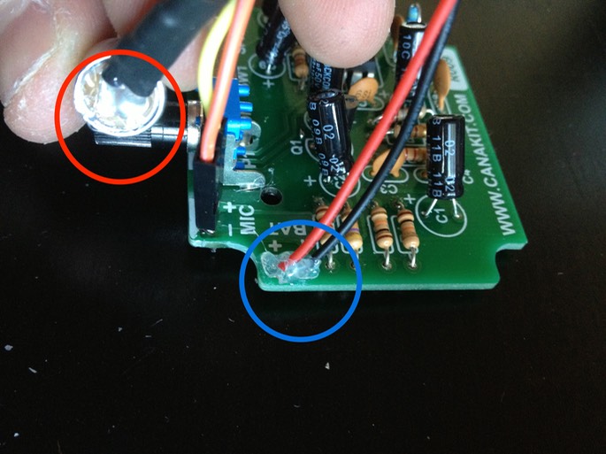
Using a heat gun, I secured the heat shrink tubing in place to add support to the connection. I also like to add a drop of hot glue to all wire connections that will be subject to stress from bending/moving around. In the next photo, I hot glued the back of the microphone (red) as well as the battery wires at point of contact with the board (blue).
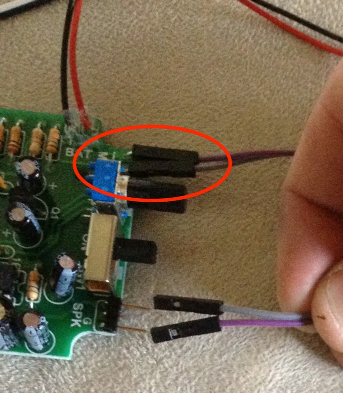
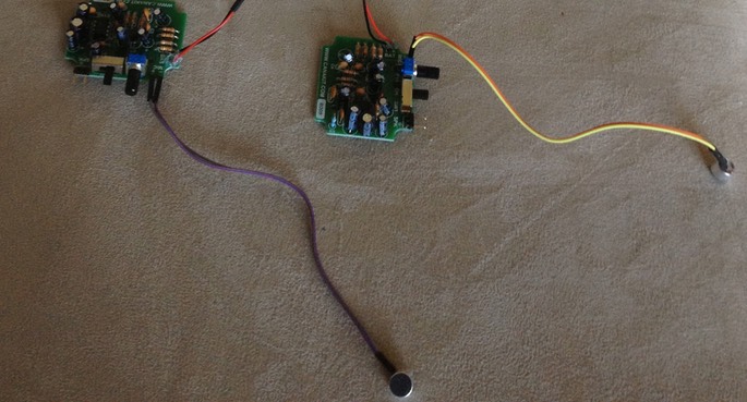
I repeat the above steps for the second board, and when all is done, the microphone setup ended up looking like this:
* * * * * * *
Wiring the Battery and Master Power Switch
Even though these amplifier boards have a built-in on/off switch, I did not relish the idea of having to dig into the lid to flip two awkwardly-positioned switches each time I wanted the system on or off. Instead, I wanted to be able to power the assembly on using a single, easily accessible master switch. I also wanted to have everything powered by a single 9v battery; this would reduce the system's battery life, but gain valuable real estate for more upgrades. The halved battery life isn't that big of a deal since realistically, you will be using the system sporadically, only when needed.
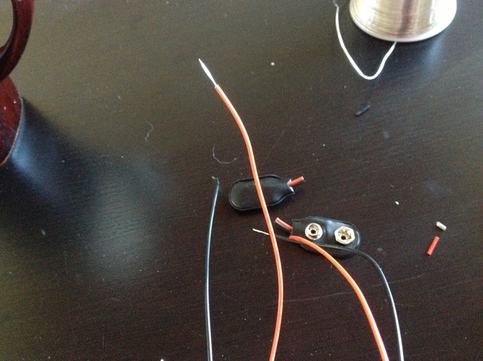
So, I cut the snap connectors off the battery wire on each board, and stripped the wires.
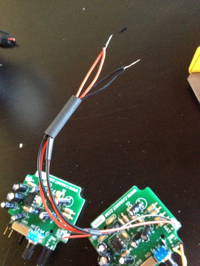
I then gathered up the wires using more heat tubing, twisted both red (+ve) wires together, and did the same with the black (-ve) wires.
Next, I used two single Dupont wires with the connectors cut off to extend the red and black wires respectively, essentially creating a single +ve and a single -ve.
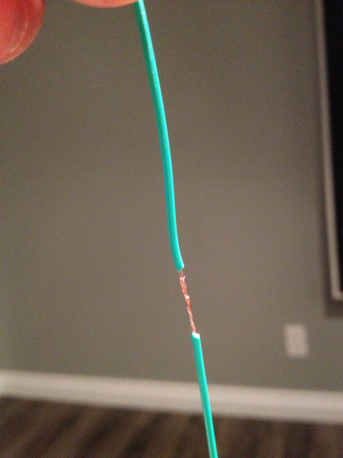
NOTE: When I need to quickly connect two wires, this is how I do it without soldering or using any type of connectors. I strip and then twist each end, and then loop them like this:
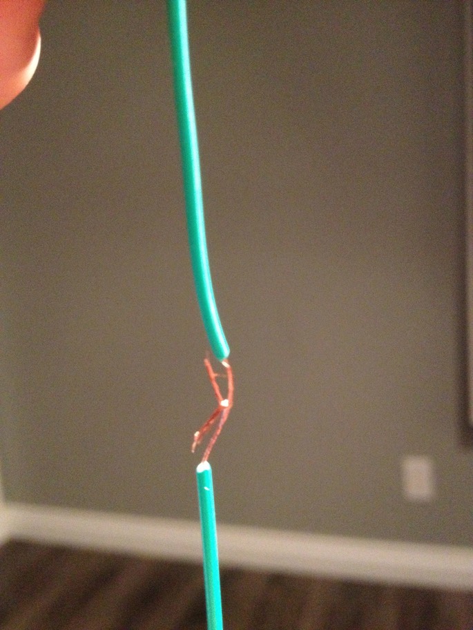
I then twist the wires together like this,
I then slide a piece of heat tubing over one end, and use a heat gun to seal the naked joint.
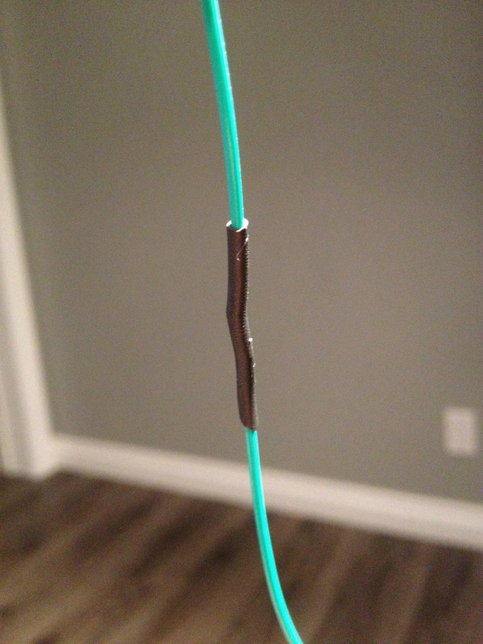
Make sure to slide the heat tubing onto the wire BEFORE you connect and twist the wires together, especially when working with branching wires. I don't know how many times I've connected multiple things together only to realize I missed the heat shrink, having to pull everything apart again. Anyway, back to the story...
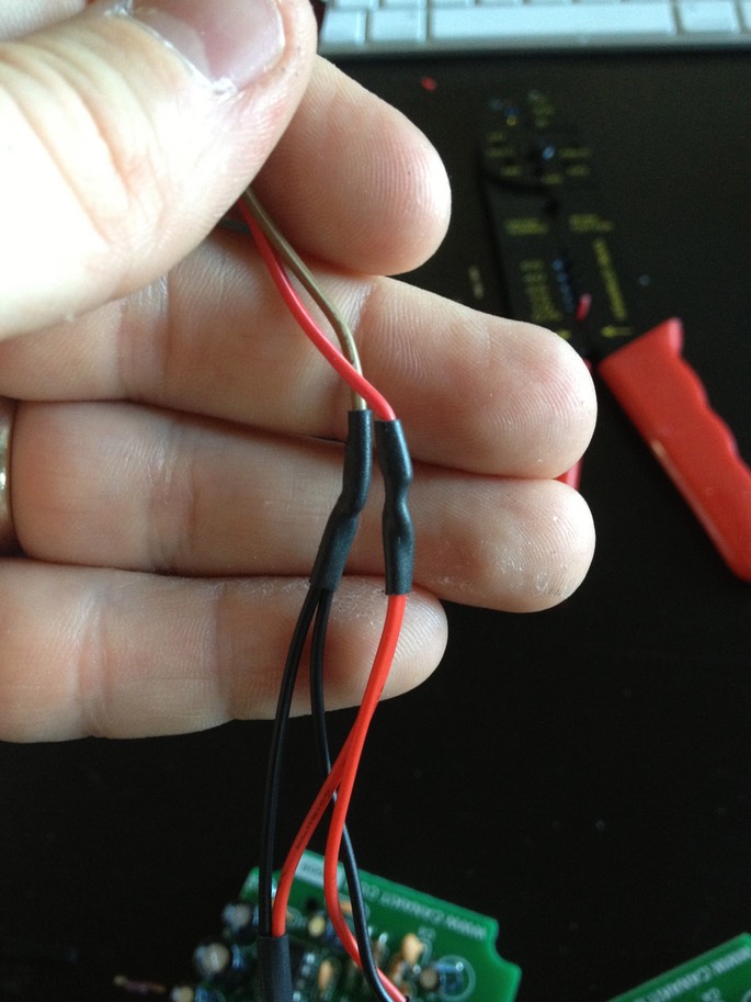
Next photo shows the two sets of red and black wires gathered up into single +ve and -ve lines.
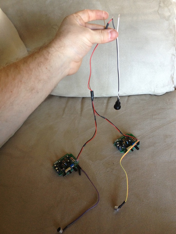
To wire the switch, hook the red wire through one of the contact loops on the switch - it doesn't matter which one, since both are technically +ve. (What a switch does is create a break in the wire that carries the current from the battery, allowing one to turn the current and thus the system on and off.) Then connect another wire to the other contact loop on the switch, and connect that to the positive wire coming out of the battery holder. (In the following photo the colours are reversed because I used different coloured wires from the Dupont pack. For the sake of explanation however, think of both of them as "Red" or +ve). Notice the still expanded heat shrink; once the wires are connected to the switch loops, and twisted to make a good connection, you would slide the heat tubing over the terminals and seal them in place with a heat gun.
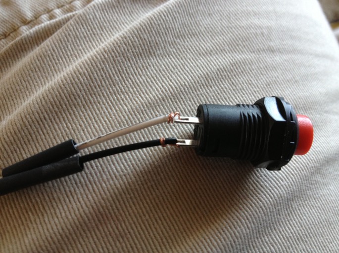
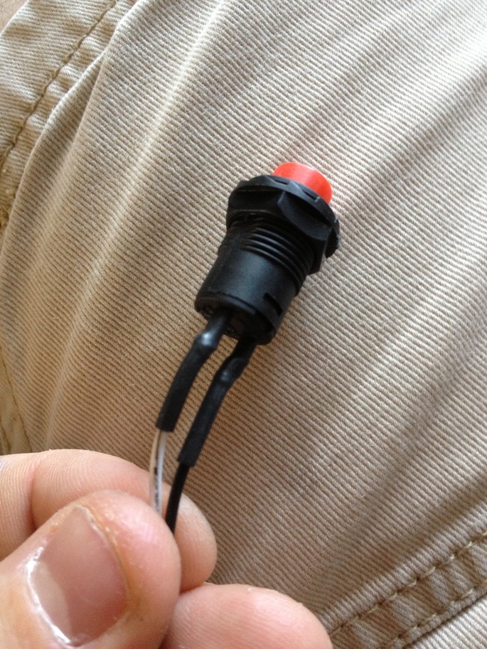
Here you can see the +ve red wire being extended (via black wire to the switch) and continuing down the circuit as as white wire.
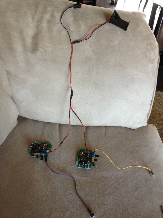
Following this, connect the +ve wire we just talked about to the positive wire (once again red) coming out of the battery holder via the same loop, twist and heat shrink method discussed above, and the negative wire coming out of the amplified board assembly to the black wire coming out of the battery holder. The final power setup should look like this:
* * * * * * *
- Environment Amplification System (EAS) DIY - Part 1
Environment Amplification System (EAS) DIY - Part 2