I've always wondered: if Stormtrooper helmets were real (well, of course they're "real", but you know what i mean), what they would look like on the inside, and the kind of electronics and gadgets they would actually have.
So, I took my eFX helmet and made it "functional" with a voice amp, fan, and amplified external audio pickups to give you that truly enhanced Stormtrooper hearing - in stereo! The real test however, was not only to stuff all the electronics inside and leave enough room for a head, but make everything look clean and neat with no glue, tape or other telltale signs of kitchen junk drawer engineering showing anywhere. Simply put, I wanted it to look awesome.
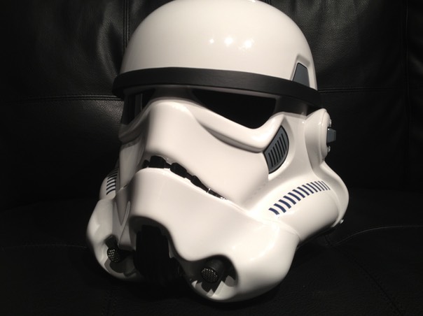
And this is what I came up with…
DIY External Amplification System Tutorial
Due to the overwhelming requests and questions I've received about this mod, I purchased another eFX helmet with intent to do a comprehensive DIY tutorial. Check it out below!
* * * * * * *
Tools for the Job
If you are interested in building your own EAS, here is the list of things you will need.

1. Drill with a 3/8 drill bit (3/8 is the exact diameter you will need to dril to fit the electret microphones through the helmet wall)
2. Soldering iron and solder
3. Wire crimp tool
4. Male - Female Dupont wire (I used 20mm length, though you can use 30mm as well; look on eBay - I bought hundreds for just a few bucks!)
5. 1" thick foam (or any other kind of semi-rigid padding material)
6. Heat shrink wire tubing (I used 3 different diameter types)
7. Superglue (save your money, and buy the dollar store kind!)
8. Industrial sticky velcro (hook and loop)
9. Heat gun
10. Scissors
11. Lighter
12. Loom (optional, but makes organizing wires easy)
13. Electrical tape
14. 9v battery holder (you can get 10 of these for $10 on eBay).
15. Electret microphone amps from Canakit.com
16. Glue gun and glue sticks (dollar store)
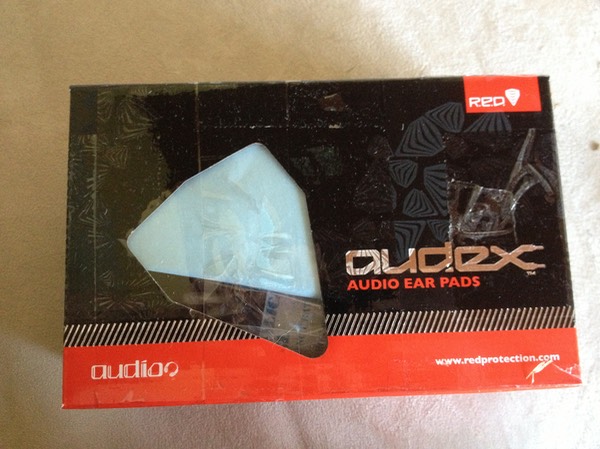
17. Ear pads with earphones in them (<-- google this phrase, and see your options). I used Burton Red Snowboard Helmet Audex Audio Earpads kit.
WARNING!
I am NOT an electronics expert, and in fact would classify my knowledge of electronics as less than amateur. The way I do things isn't "right" by any stretch of the imagination; therefore, what I am about to demonstrate only shows "how I DID IT", and not necessarily how YOU SHOULD do it. If you know a better or more correct technique for soldering / desoldering / connecting wires/crimping etc., by all means use that! If you don't, then doing what I did will at the very best give you the same results I got in doing this project.
18. Push on/ Push off (latching) switch (eBay)
* * * * * * *
Modifying the Speaker Setup
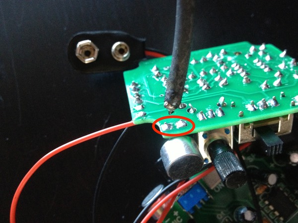
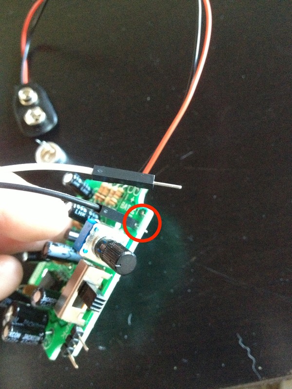
First thing I did is desolder the microphone that is hardwired onto the circuit board. Using a soldering iron, I applied heat to these two contact points until the solder melted, and pulled the microphone off the board. (You may need an extra pair of hands for this since heating the solder and pulling the microphone must pretty much be done at the same time. The mic should slide out smoothly; if it doesn't, the solder it still hard, and any wiggling or bending of the contacts will snap the microphone connectors.)
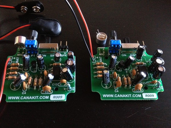
After the microphoned came off, it looked like this (on the right):
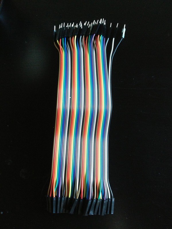
Next, I wanted to put the microphone on a wire, for which I used the 20mm m/f Dupont cables. These wires are dirt cheap, and are fantastic for making quick connections with the use of the male/female ends (especially handy when making connections to these AMP boards, as we shall see in a moment). In situations where you don't need the connectors, just cut them off, and use the cable as regular wire.
The ones in the photo came in a bundle of 40, which allows you to peel them off one by one, or in strands of 2, 3, 5 etc. For the next step, we will need to peel off a strand of two.
With the microphone removed, I heated up the now microphone-less solder joints as before, and at the same time inserted the male end of the Dupont cable into the hole about 3/4 of the way in.
You don't want to insert it all the way in, as you want to allow some room for the male pin to bend forward in order to decrease the vertical profile of the board, like this:
Next, I cut off the female ends of the cables I just attached, stripped the ends using the wire stripper tool, fit a little section of heat shrink tubing over each end, and soldered the ends to the appropriate microphone "leg" terminals. If you are not certain which is which, the negative is the one with a little tab that runs under the microphone housing.
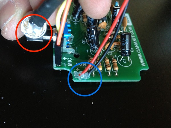
Using a heat gun, I secured the heat shrink tubing in place to add support to the connection. I also like to add a drop of hot glue to all wire connections that will be subject to stress from bending/moving around. In the next photo, I hot glued the back of the microphone (red) as well as the battery wires at point of contact with the board (blue).
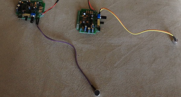
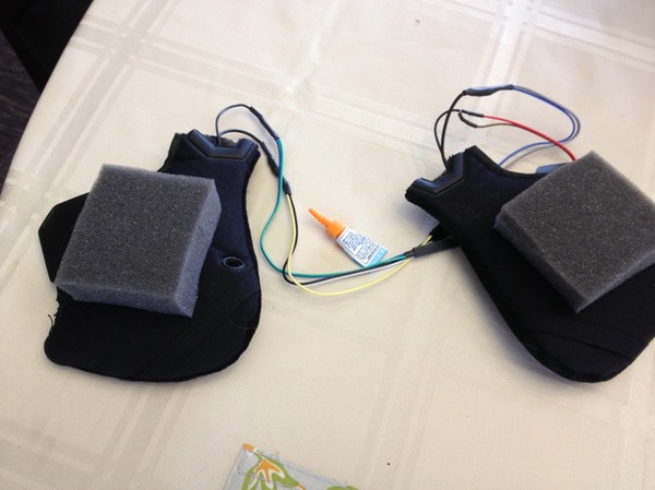
I repeat the above steps for the second board, and when all is done, the microphone setup ended up looking like this:
* * * * * * *
Wiring the Battery and Master Power Switch
Even though these amplifier boards have a built-in on/off switch, I did not relish the idea of having to dig into the lid to flip two awkwardly-positioned switches each time I wanted the system on or off. Instead, I wanted to be able to power the assembly on using a single, easily accessible master switch. I also wanted to have everything powered by a single 9v battery; this would reduce the system's battery life, but gain valuable real estate for more upgrades. The halved battery life isn't that big of a deal since realistically, you will be using the system sporadically, only when needed.
So, I cut the snap connectors off the battery wire on each board, and stripped the wires.
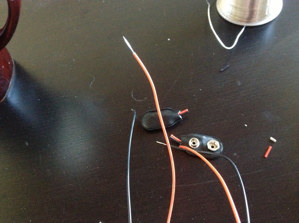
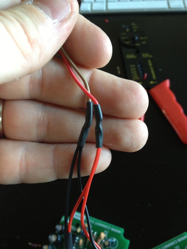
I then gathered up the wires using more heat tubing, twisted both red (+ve) wires together, and did the same with the black (-ve) wires.
Next, I used two single Dupont wires with the connectors cut off to extend the red and black wires respectively, essentially creating a single +ve and a single -ve.
NOTE: When I need to quickly connect two wires, this is how I do it without soldering or using any type of connectors. I strip and then twist each end, and then loop them like this:
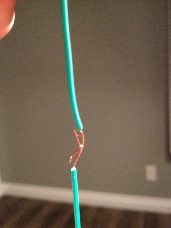
I then twist the wires together like this,
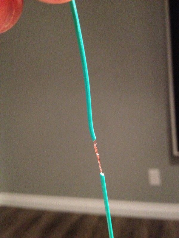
I then slide a piece of heat tubing over one end, and use a heat gun to seal the naked joint.
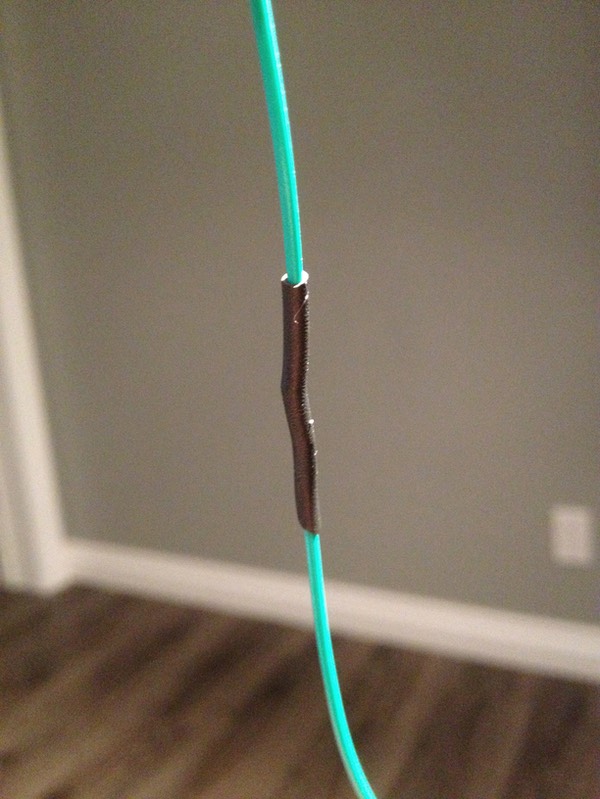
Make sure to slide the heat tubing onto the wire BEFORE you connect and twist the wires together, especially when working with branching wires. I don't know how many times I've connected multiple things together only to realize I missed the heat shrink, having to pull everything apart again. Anyway, back to the story...
Next photo shows the two sets of red and black wires gathered up into single +ve and -ve lines.
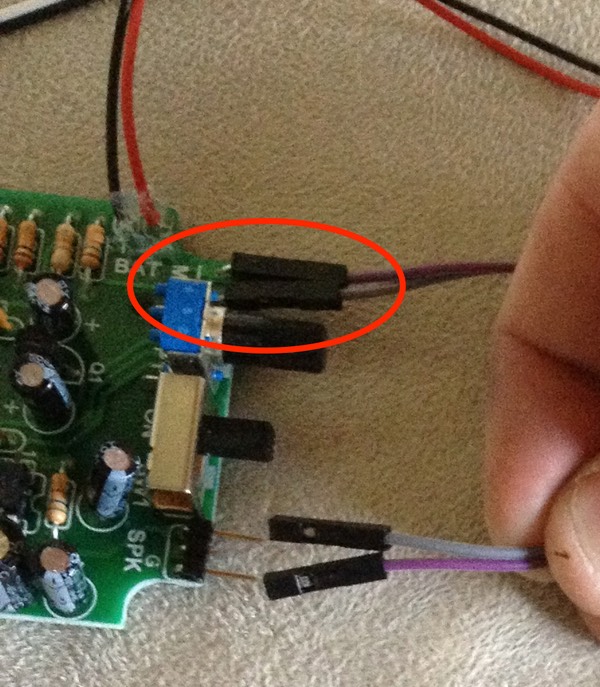
To wire the switch, hook the red wire through one of the contact loops on the switch - it doesn't matter which one, since both are technically +ve. (What a switch does is create a break in the wire that carries the current from the battery, allowing one to turn the current and thus the system on and off.) Then connect another wire to the other contact loop on the switch, and connect that to the positive wire coming out of the battery holder. (In the following photo the colours are reversed because I used different coloured wires from the Dupont pack. For the sake of explanation however, think of both of them as "Red" or +ve). Notice the still expanded heat shrink; once the wires are connected to the switch loops, and twisted to make a good connection, you would slide the heat tubing over the terminals and seal them in place with a heat gun.
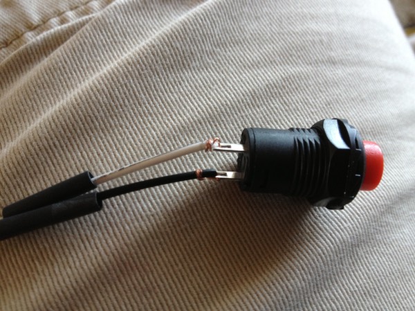
Here you can see the +ve red wire being extended (via black wire to the switch) and continuing down the circuit as as white wire.
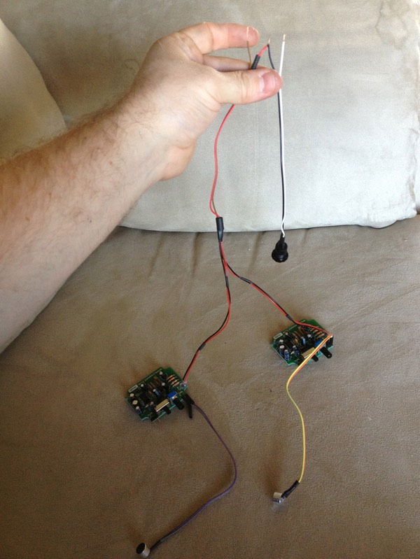
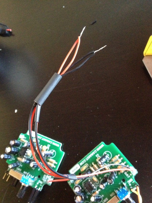
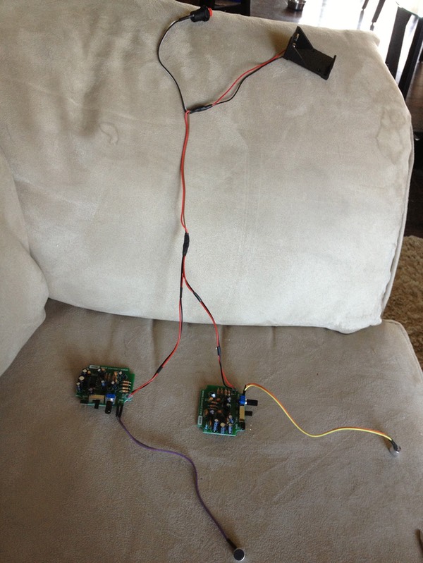
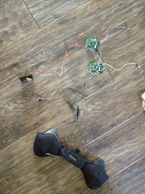
Following this, connect the +ve wire we just talked about to the positive wire (once again red) coming out of the battery holder via the same loop, twist and heat shrink method discussed above, and the negative wire coming out of the amplified board assembly to the black wire coming out of the battery holder. The final power setup should look like this:
Wiring the Ear Speakers
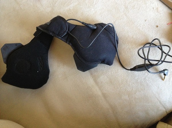
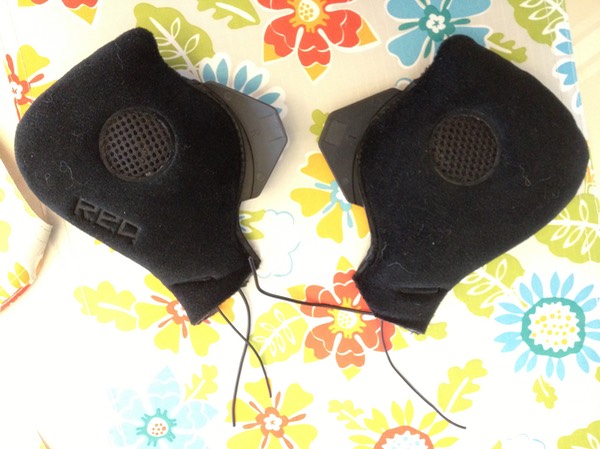
For ear speakers, I used the Burton Red Snowboard Helmet Audex Audio Earpads kit I bought online at a discount. These are exactly what the title says: earpads containing stereo speakers. They come with a detachable stereo volume control cable that can be plugged into an iPod, other MP3 players, and in our case, fully adaptable for the EAS!
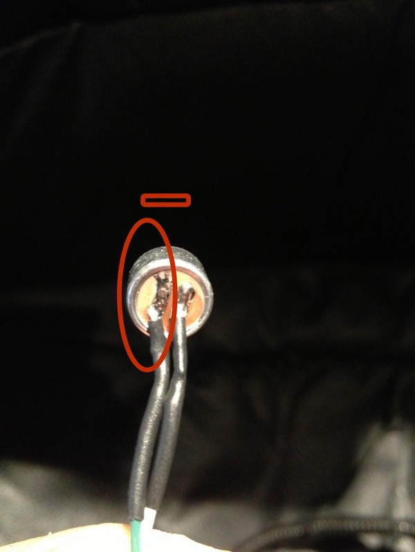
To adapt these for use with my system, I cut off the L shaped connector jack, exposed the wires (which are really really thin!)...
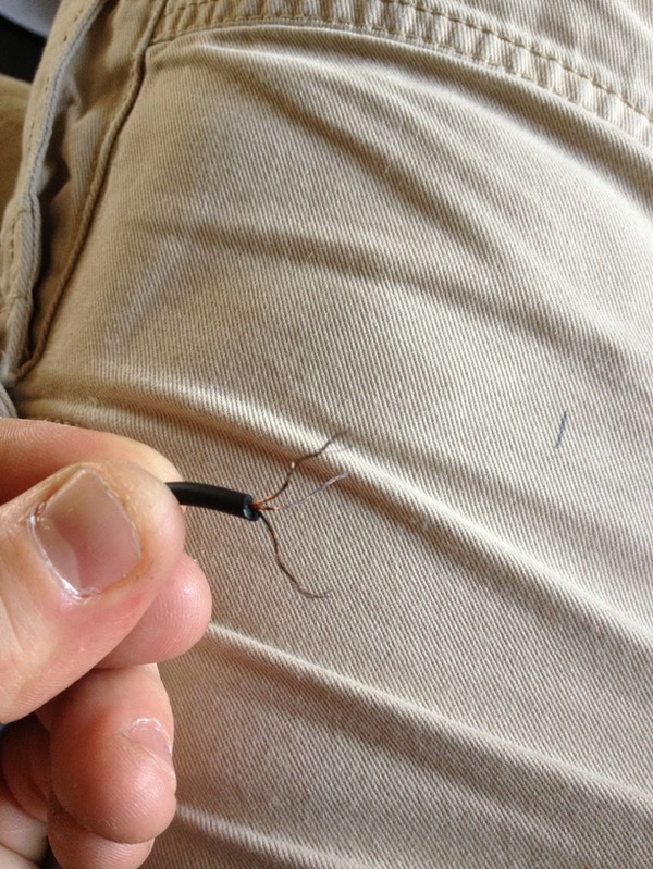
... used a lighter to burn off the white isolation strands on the wires themselves about half way. (You need to remove that stuff somehow or whatever you connect to them will have a poor connection, and using a lighter made the most sense. You only want to burn it off half way; if you go too far up the wire - toward the black - you risk of exposing too much, which can lead to accidental cross wiring.)
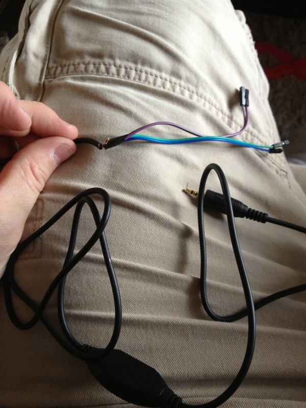
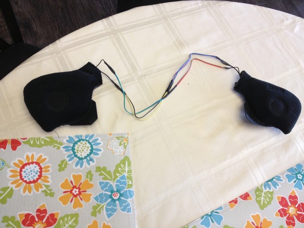
There are three wires inside the main black cable: one for the left channel, one for the right, and one ground. The L and R wires are red and green, while the ground wire is copper.
Using two Dupont wires, cut off the male ends and strip the remaining ends. Using the same loop, twist and heat shrink method, connect the red and green wires to the first and second modified Dupont wire respectively. These will be your live L and R channel wires that will connect to the appropriate terminal on each amp (one per amp).
Now, prepare another duo of Dupont wires the same way (cut off the male tips - sounds rather painful….HA!), and connect BOTH OF THESE TO THE REMAINING COPPER WIRE using the same loop, twist, heat shrink method. These two new wires will be your ground wires, completing the circuit for each board.
So, in a nutshell, you will have 3 wires coming out of the black stereo cable, two of which will feed the L and R channels via a female-tipped Dupont wire (one for each amp), and the copper cable, which will fork out into two female-tipped Dupont wires which will act as ground.
Now, plug one of the positive ends we've just made (let's call it Left) into the live speaker terminal one one board, and the other positive end (R ) into the live speaker terminal on the other board, and fit the remaining wires onto the ground prongs on the boards.
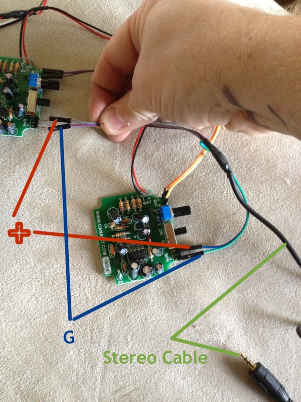
And, viola! the EAS system is now complete!
* * * * * * *
Preparing the Helmet
Given the amount of questions and feedback I've received since posting my video, I purchased another eFX helmet just so I could demonstrate what I've done in more detail.
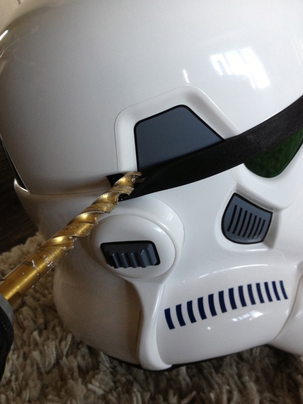
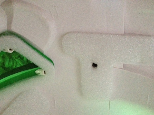
I peeled up the rubber brow strip (which eFX seems to have glued on using cold fusion), and using a 3/8 drill bit, drilled a hole in this location on both sides of the helmet. Now, BE CAREFUL! Given its construction, the eFX helmet has 3 layers of thick plastic to go through, so drilling like this is not an issue. However, if you have any number of other makes of the helmet, the plastic will be MUCH thinner, so it could do well to start with a smaller bit to make a pilot hole, and carefully work your way up to the 3/8. I did all these modifications to my AP helmet as well, and I had to be much more careful drilling given how thin the plastic is!
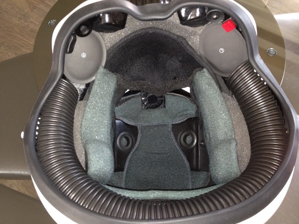
I did not modify or paint the inside of this lid, so here you can see the inside of the eFX with its original factory padding in all its glory.
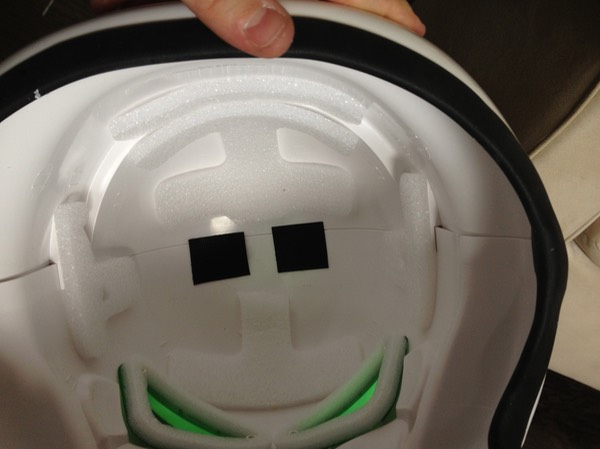
Next, I glued in some velcro pads (hook) where the Amp boards would go...
(NOTE: if you have any of the non-licensed helmets, make sure you wash the inside surface with soap and water to remove any mold release agent that may be present, or the velcro will not stick!)
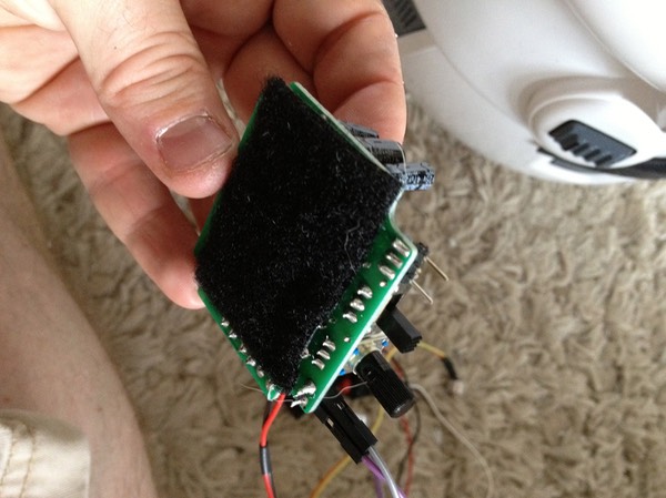
and added the loop straps to the underside of the boards.
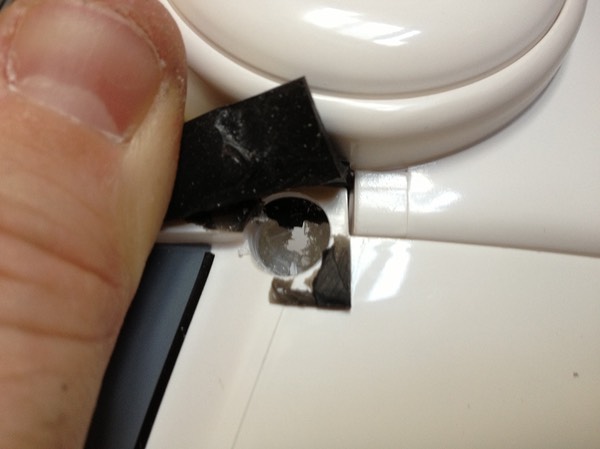
I stuck the boards inside, and fed the microphone through the holes I drilled. The microphones fit PERFECTLY. Nice and snug.
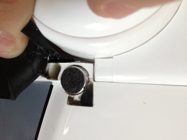
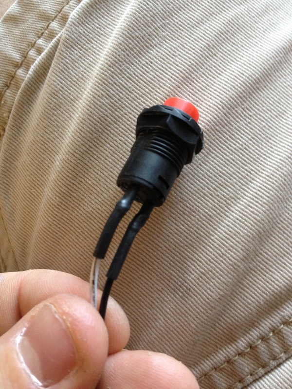
I attached the battery holder using velcro as well, and super glued the switch in.
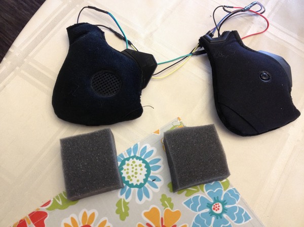
Next, I realized the headphone pads were too close together inside the eFx given its larger build. (I used home made ear pads inside my AP lid, so this was a non-issue in that build). So I cut the center ridge out (careful not to cut the wires). However, even with this was removed, the wires housed inside did not provide much slack. The only thing left was to cut the wires and extend them using ones from my Dupont pack. This was unfortunate because it created more work :).
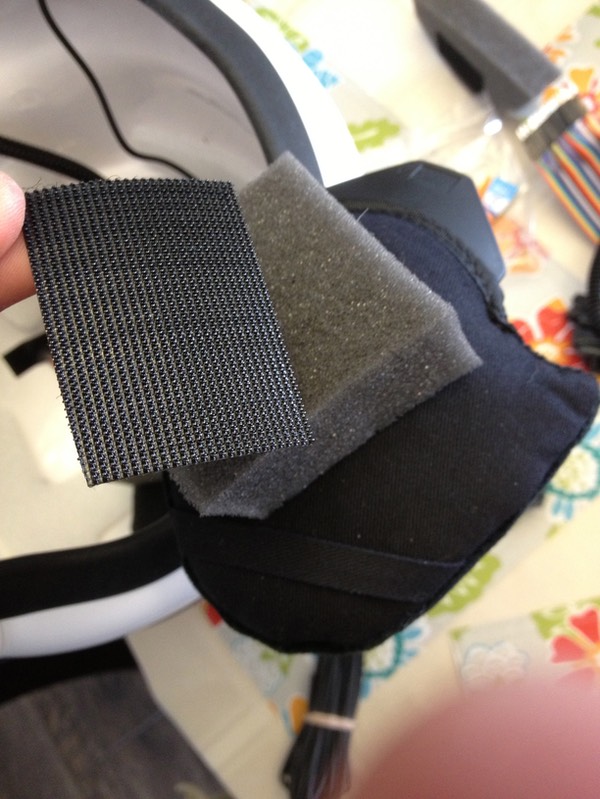
Once I got this accomplished, I superglued little squares of 1" foam I use for my Sith Acolyte Masks to the back of each ear pad to build up the thickness.
I attached some sticky industrial velcro hook to these (which stick really well to foam),
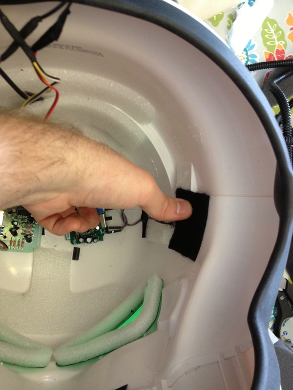
and attached corresponding loop to the inside of the helmet.
With the earpads installed, now it's a matter or cleaning up the look!
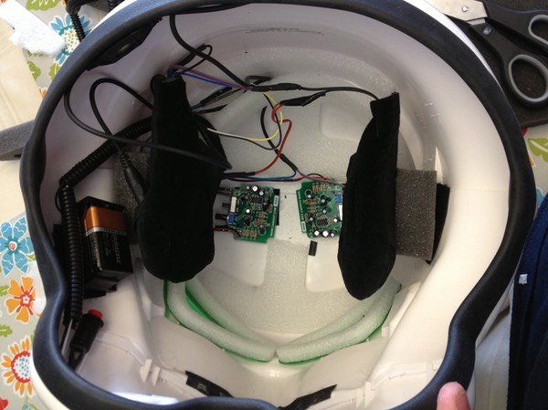
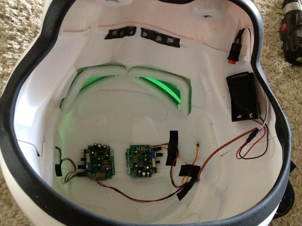
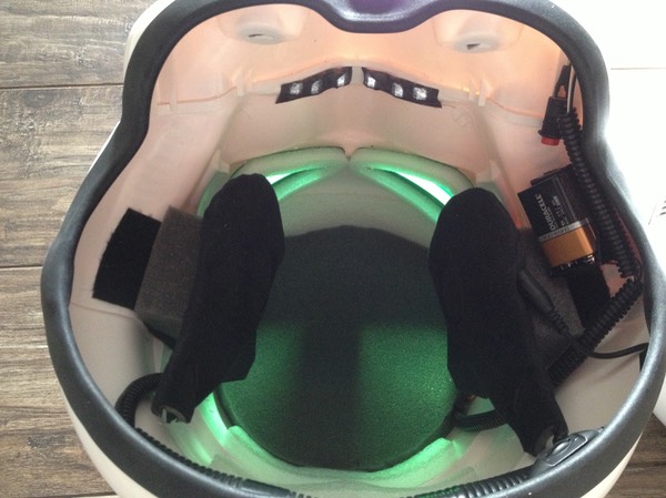
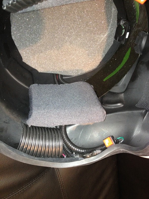
Lastly, I cut a rough circle out of the aforementioned 1" foam for dome padding (which also conceals the electronics), and gathered the stray wires with loom.
* * * * * * *
Finished Helmets with EAS
At last, after about 3 hours of work, here is the final product: a stormtrooper helmet with a fully functional, stereo environment amplification system! And the best parts: it's completely hidden from outside view, and still allows a ton of room inside the lid for fans, transmitters, and whatever else you want to upgrade with!
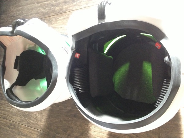
Here is the eFX next to my AP helmet outfitted with the same system.
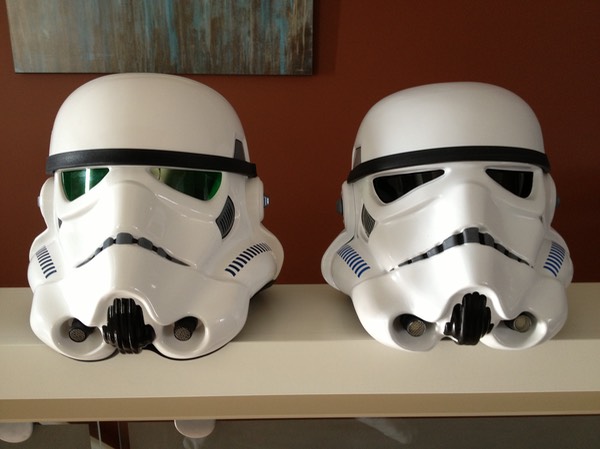
In the next photo, AP on the right, eFX on the left:
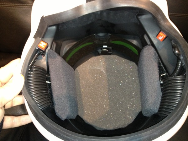
More photos of the AP (which is painted black on the inside, and upgraded with a fan, and Trooperbay lens):
Thanks for looking, and happy crafting!
* * * * * * *